Abstract: Different energized electrons (due to different potential difference) can pass through a conductor in the same or opposite direction simultaneously at any given instant. The conductor may be metal, graphite or water. In the case of water, the result obtained is slightly different from metal or non-metal graphite, due to the special characteristics of water which is discussed in this paper.
[Whenever any foreign material is dipped into water, the orientations of diploes of water molecules rearrange themselves, as a result of which the electrical energy of water changes. This change governs the energy contents of succeeding dilutions whatever the foreign material may be, eg. sodium chloride8 or DNA11.]
A conductor is electrically neutral in the absence of any electrical source. It carries current by simultaneous gain and loss of electrons, i.e. gain of electrons at one point and loss of electrons at another point at a particular time.
Whenever the negative terminal of a battery or a cell is connected to a conductor, electrons of the conductor get the energy equivalent to the energy of electrons of the source, (arising out of its negative terminal) and unless and until a positive terminal (electron deficient end of the battery ) is attached to the conductor , the energized electrons in the conductor never flow , i.e. energized electrons in the conductor (due to the negative terminal of the battery) are very selective for their onward progress to a deficit zone.
This reflects that if two different energized electrons are there in the conductor (due to two different negative terminals) both will find their way only to their respective deficit zone, from which it is created.
The two types of energized electron (in respect of their energy content) may travel in opposite directions or in the same direction at any particular instant as shown below .
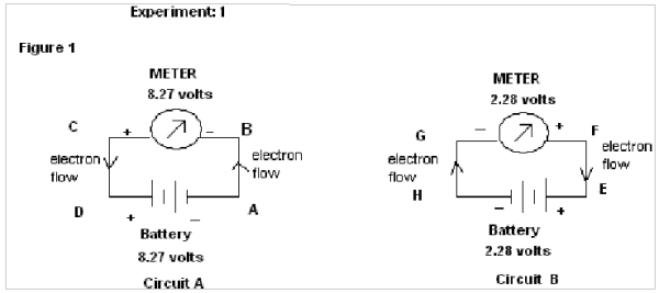
EXPERIMENT : 1 (For SAME direction of flow of electrons)
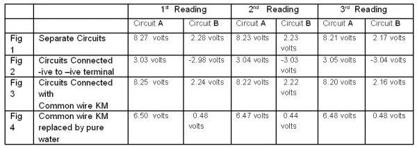
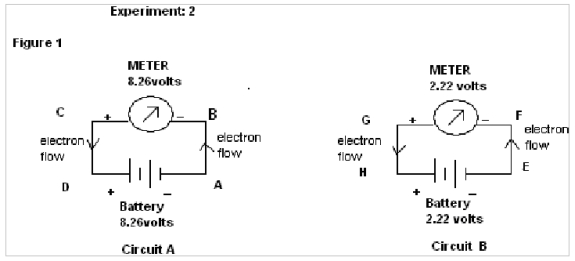
In this experiment two different circuits are prepared from two different sources of Battery of emf 8.27 volts & 2.28 volts.
In figure 1, in circuit A the electrons flow from A to B & in circuit B the electrons flow from H to G. It therefore shows that the electrons flow in same direction through both the circuits(i.e upward).

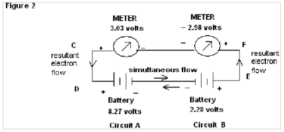
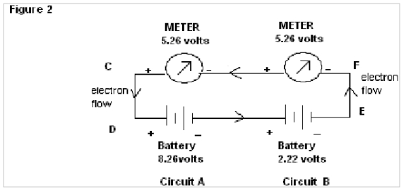
In Fig.2 , wherein wires AB & HG are removed and the separated circuits are amalgamated it is found that a Meter connected with circuit A shows a positive reading of 3.03 volts whereas a meter connected with circuit B shows negative reading of –2.98 volts.
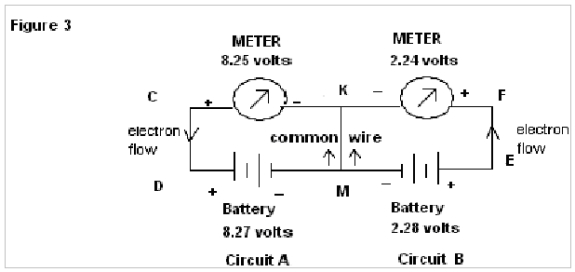
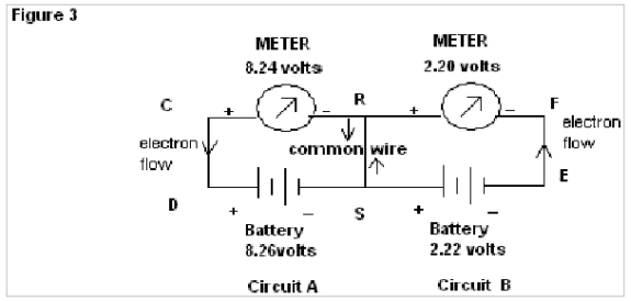
Now in Fig 3 when a common wire KM is connected, the meters connected to the Circuits A & B show readings of 8.25v & 2.24 volts respectively (i.e almost that of source battery), here electrons flow in the same direction through the common wire KM.
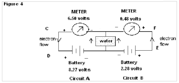
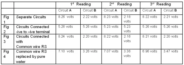
In Fig.4 when common wire KM is replaced by Pure water the meter connected to circuit A shows comparatively less fall in reading, whereas the meter connected to circuit B shows a deep fall ( initial 2.28 volts to 0.48 volts) in its reading with respect to source battery.
Three such readings are tabulated below:
EXPERIMENT : 2 (For OPPOSITE direction of flow of electrons):
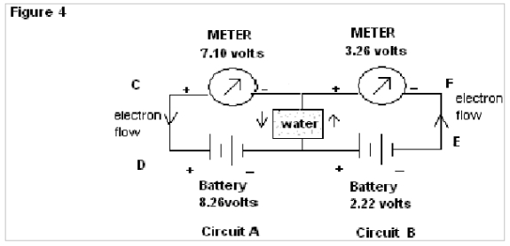
In this experiment two different circuits are prepared from two different sources of Battery of emf 8.26 volts & 2.22 volts.
In figure 1, in circuit A the electrons flow from A to B and in circuit B the electrons flow from G to H. It, therefore shows that the electrons flow in the opposite direction through the circuits.
In Fig.2 , wherein wires AB & HG are removed and the separated circuits are amalgamated, it is found that both the meters shows reading of 5.26 volts.
Now in Fig 3 when a common wire RS is connected the meters connected to the Circuits, A & B shows readings of 8.24v & 2.20 volts respectively (i.e almost that of source battery). Here electrons flow in the opposite direction through the common wire RS simultaneously.
In Fig.4 when common wire RS is replaced by pure water the meter connected to circuit A shows comparatively less fall in reading whereas the meter connected to circuit B shows a deeprise ( initial 2.22 volts to 3.26 volts) in its reading with respect to the source battery.
Three such readings are tabulated below:
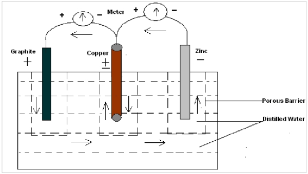
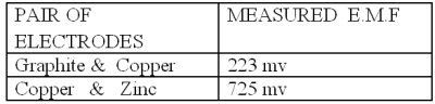
Experiment 3 In this experiment three electrodes of different substances (here Copper, Graphite and Zinc ) are dipped in water (pure/ distilled ) and emf is measured simultaneously. It is found that one of the metal electrodes acts as a negative and positive electrode simultaneously, i.e in respect of one electrode it is positive and other it is negative. Here copper behaves as negative with respect to graphite and negative with respect to zinc at the same time as shown in figure :
Discussion : In all the above three experiments it is found that electrons can flow through a conductor in the same or opposite direction simultaneously.
In Fig.2 of exp. 1 the negative readings of the meter of circuit 2 are obviously due to simultaneous flow of electrons in both the directions, but showing results of only Resultant Flow in the meter (i.e algebraic mean of the two batteries).
In Fig.3 of exp. 1the electrons flow through the common wire KM in the same direction and show almost the same emf as that of the source batteries. But when the common wire KM is replaced by water (as in Fig.4 of exp.1) a deep fall in emf, as shown by the meter in Circuit B (from 2.28 to 0.48 volts) is found in comparison to that for circuit A. Here it is observed that no such result is found in the case of common wire KM, but when water is used there is a deep fall in the reading for the meter of circuit B. This abnormality of readings can again be explained by the property of water to change its orientation of dipoles according to the applied emf. In the instant case the orientations of water molecules due to the applied emf from the source of 8.27 volts & 2.28 volts being of the same nature, the resistance to flow of electron decreases and as a result, resultant emf as shown by meter in circuit B has a deep fall (since V=IR).
In Fig.2 of exp. 2 the electrons flow in one direction, so the emf shown by the meters is the algebraic mean of the two batteries.
In Fig.3 of exp. 2 the electrons flow through the common wire RS in the opposite direction and shows almost the same emf as that of the source batteries. But when the common wire KM is replaced by water (as in Fig.4 of exp. 2), there is a deep rise in emf, as shown by the meter in Circuit B (from 2.22 to 3.26 volts) in contrast to fall in circuit A (from 8.24 to 7.10 volts). Here it is observed that no such result is found in case of common wire RS; but when water is used there is a deep rise in readings for the meter of circuit B. This abnormality of readings can again be explained by the property of water to change its orientations of dipoles according to the applied emf. In the instant case, the orientations of water molecules due to the applied emf from the source of 8.26 volts & 2.22 volts being of opposite nature the resistance to flow of electron increases, as a result of which resultant emf as shown by meter in circuit B has a deep rise (since V=IR).
In Exp. 3 it is also found that a single electrode acts as a positive and negative terminal simultaneously during production of emf, i.e electrons pass in both directions simultaneously.
Conclusion :
1. Each emf produces a specific energized electron which moves through the conductor only to its deficit zone (i.e; through the shortest possible way to the source of its production) in the same or opposite direction simultaneously.
2. As stated in our earlier works, the orientations of dipoles of water molecules are a key factor in explaining homeopathic dilution ( i.e; a particular electrical energy content of water is due to specific orientations of diploes of water molecules). Herein it is once again confirmed that the results obtained for different applied emf in water is solely due to different orientations of diploes of water molecules.
REFERENCES:
[1] Physical Chemistry, P C Rakshit (Revised 4th Edition) 1980, Published by S C Rakshit, Kolkata , India
[2] Concise New Organic Chemistry, J D Lee, 1987, 3rd Edition, VanNostrant Reinhold Publishers, U K
[3] Physical Chemistry, S Glasstone, 2nd Edition, 1946
[4] E:Electrochemistry.thm, Composed by J B Calvert (Last revised 23rd Nov., 2002)
[5] N A Lange, ed, Handbook of Chemistry , 10th Edition (Newyork, McGrow Hill 1961)
[6] R C Weast, ed, Handbook of Chemistry and Physics (Cleveland: Chemical Rubber Publishing Co., 1975)
[7] L Pouling , General Chemistry, 1970 (NewYork, Dover)
[8] R. Amin, B. Chakraborty and F. Rahaman, THE HOMEOPATHIC DILUTION – A NEW EXPLANATION, SIMILLIMUM , Journal of Homeopathic Academy of Naturopathic Physicians, Vol. XXI Summer/Fall (2008) , USA.
[9] R. Amin, and B. Chakraborty, THE ELECTRICAL ENERGY OF SUBSTANCES: THE SECRET OF HOMEOPATHY SIMILLIMUM , Journal of Homeopathic Academy of Naturopathic Physicians, Vol. XXII ,Fall Winter(2009) , USA
[10] R. Amin, and B. Chakraborty, GENERATION OF ELECTRODE POTENTIAL OF AN ELECTRODE- A NEW EXPLATION, SIMILLIMUM , Journal of Homeopathic Academy of Naturopathic Physicians, Vol. XXIII, Fall Winter(2010), USA
[11]. Recent works of Prof. Luc Monteigner.


Sir, your voltmeters must be faulty or of poor quality. When ever we connect a volt meter to a voltage source through medium conductor such as water, it must show full battery voltage. If it is not then it has poor internal impedence. What you are measuring is resultant drop due to difference between water resistance and meter internal resistance.
Dear Sir,
While thanking you we would rather request you to go through our earlier works and get yourself familiar with some interesting properties of water that explains Homeopathy.
Devidas is correct; your meter is wrong. Next time select a meter with what is called very high input impedance. Use a high quality digital multimeter for example. Its is more important if you are using DI water.
Dear Sir,
i) We have cited our results for pure/distill water so question of D.I water does not arise.
ii) Make it clear first whether you agree or contradict with our result i.e: “The electrical energy can flow through conductor(metal or water) in same or opposite direction simultaneously.”
i) So this information makes my case even stronger: do you realize what will be the resistance of pure water? (it will be >10 Mohm.cm).
ii) I neither agree nor disagree as I have not read the subject in detail. I was just commenting on your experimental results. It will be useful to see the same experiment (that you claim supports your hypothesis) with a very good equipment. We see such results always at the lab all the time when measuring high impedances.
While I appreciate your curiosity in trying to find and reason the science behind the working of homeopathy (which has been explained well by some excellent works by material scientists like Dr.Rustum Roy, Dr.C.W Smith, Dr.Martin Chaplin and a few others who have done pioneering research over last few decades), your experiments and observations as outlined here are absurd and laughable.
Whatever meters you have used to measure the voltages, voltmeters (and multimeters in the voltage measuring modes) are designed to have very high-impedance so that they do not load the circuit under measurement, in order to measure the true emf that exists between the measuring points. When you connect two voltmeters in series and measure some emf between two points, you should realize that you are not actually measuring the emf between those points.
Even though very little current flows through an voltmeter internal measuring electronics (which may have JFET or MOSFET input op-amp circuitry so as not to cause any loading), this little current when it passes through the large impedance of the second voltmeter, will cause considerable voltage drop, depending upon its impedance value, actual current that is flowing, the emf available at the measuring points, the internal circuitry of the meter and also the way you connect it (the +ve and -ve terminals) since the voltmeters are not designed to be connected and used this way (which is absurd any way to connect two voltmeters in series).
So what you are measuring in Fig-2 is wrong and absurd and does not have any meaning or value in your observations and explanations.