


Chapter 5 Methods of Potentisation
There are many ways of preparing a homeopathic potency. This chapter will attempt to unify and to relate all of them to the physics of water.
5.1 Potency Resolution Resolved
In Chapter 4, I concluded Section 4.3 with the remark that, “To measure the bandwidth of a water imprint would require an oscillator with a resolution of better than 2 parts in 107.” Since then, I have had brief access to an oscillator [1] which had a frequency resolution of 1 microHertz. This frequency corresponds to one cycle in 11½ days and gives access to circadian rhythms. With its maximum frequency of 80 MHz imprinted into water, the resonance was detectable down to 79.999 346 MHz representing a bandwidth of 1,308 Hz. From the equations in Section 4.3, the theoretical bandwidth assuming that the energy of the quantum fluctuations in the number of coherent 80 MHz photons equals the energy of thermal vibrations at 15°C comes to 6,720 Hz. I may only have measured the tip of the iceberg but theory and experiment have reached the same ‘ball-park’.
5.2 Succussion by Contact
The information in a homeopathic potency can slowly imprint into water by contact without need for any mechanical succussion. As an example, a glass tube containing ‘erased’ water (see Section 4.6) was placed in a beaker of water imprinted with a range of frequencies. The higher frequencies imprinted more quickly than the lower frequencies as shown in Figure 1. This suggests that the potentisation process does not necessarily require energy other than thermal excitation and that imprinting awaits the random arrival of the correct frequency component in the thermal noise to effect a potentisation.
In Figure 1, the two theoretical lines shown were calculated from the equations in Section 4.3 for random (incoherent) and coherent photons respectively. As shown in Figure 10 of Chapter 3, the bandwidth of a resonance is related to the rise and decay times. As Froehlich used to remark, onset time delay is a hall-mark of coherence.
The potentisation from water-to-water through glass more or less follows the incoherent line which is based on the uncertainty in the number of random quanta. Whereas, potentisation to a chlorided silver wire which has no potential barrier to water imprints in the times given by assuming coherent quanta. Potentisation to copper and gold fall between the two theoretical lines. Potentised copper placed in contact with copper does not transfer any potentisation.
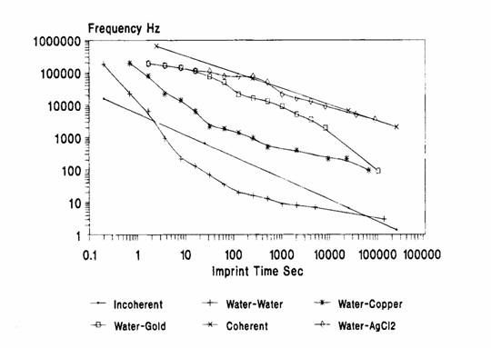
Figure 1
Time delay for potentisation by contact as a function of the frequency being imprinted.
5.3 Physical Basis of Potentisation
Potencies were originally prepared by the “Classical Hahnemanian” method of impacting of a vial on the cover of a leather-bound book. Now in addition, potencies may be prepared by vortexing, the application of magnetic fields, and the use of electronic potentisers and acupuncture apparatus. As will be shown, calculators, computers and electrical impulses in general including nerve pulse trains can potentise; it is even possible to potentise chemically.
There is one piece of physics which can cover all these modalities, this is magnetic moment. In quantum physics, the angular momentum of an isolated particle is quantised, that is it can only exist in certain states which are integer multiples of Planck’s Constant divided by 2p.
There is a quantity called the magnetic (dipole) moment which is defined as the mechanical force or torque acting on a mathematically small loop carrying a current when it is in a magnetic field of unit strength. This quantity is related fundamentally to the mechanical angular momentum by a physical constant called the gyro-magnetic ratio.
In Section 4.6 the precession of the proton spin in a magnetic field was used to account for the memory of water. The spin of the proton can account for the phenomenon of potentisation.
The angular momentum of a proton P = M w r2 where M is the mass of the proton, w is the angular velocity with which it spins (w measured in radians/sec is 2p times the frequency of rotation), r is the effective radius.
The magnetic moment of a proton mp = ½ e w r2 = 1.410 606 633 × 10-26 J.T-1
where e is the elementary charge = 1.602 176 462 × 10-19 C.
The gyromagnetic ratio g = m / P = e / 2M where M = 1.672 621 58 kg.
and for the proton gp = 2.675 222 12 × 108 s-1. T-1
Placed in a magnetic field of strength B, the proton energy change DE = 2 mp B.
The threshold steady magnetic field to effect a potentisation is ~ 5 mT (500 Gauss) and the corresponding proton energy DE = 1.4 × 10⁻²⁸ J.
If this is equated to thermal energy for n protons, n DE = kT where k is the Boltzmann Constant = 1.380 650 3 × 10-23 K-1 (K is Kelvin, the absolute temperature = °C + 273)
Then, at 15°C kT = 4 × 10-21 J
and n = 4 × 10-21 / 1.4 × 10-28 = 2.9 × 10⁷ coherent protons
In Section 4.6, it was estimated that 5.52 × 10¹⁵ protons should be available for imprinting frequencies into water. The statistical fluctuations about this number would be its square root, 7.4 × 10⁷ .
To potentise water, energy must be supplied which is sufficient to overcome thermal randomisation and the statistical fluctuations in the size of a coherence domain.
Energy calculations only show whether a hypothesis is energetically possible. They do not indicate how the transition from the initial to the final state takes place.
5.4 Potentisation by Mechanical Succussion
If succussion is able to change the proton angular momentum and thence the magnetic moment, this should be apparent if succussion is carried out in different magnetic field strengths. Preliminary experiments by dropping a vial of water from different heights onto a wood surface showed that the kinetic energy at impact did not matter but what did matter was the change in momentum. The volume of water used did not matter either. Thus, one must conclude that the effective mass in this case is that of a coherence domain as described in Sections 4.5 & 4.6.
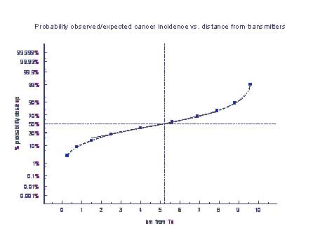
Figure 2
The impact velocity of a glass tube of water suspended as a pendulum against an equal tube similarly suspended but at rest is plotted as the ordinate. The abscissa is the strength of magnetic field at the point of impact required for potentisation to occur.
Accordingly, a glass tube of water was suspended as a pendulum and made to impact against an equal tube similarly suspended but at rest. The strength of magnetic field at the point of impact required for potentisation to occur was found to decrease as the velocity at impact increased as shown in Figure 2. Momentum is mass times velocity.
The impact velocity v for potentisation in the Earth’s magnetic field was 4.5 m/s. The impact was against a stationary tube. With simplification, the change of momentum of a coherence domain will be Mv but, this needs to be translated into a change in angular momentum M w r2. If the Compton Wavelength for the proton (1.3×10⁻¹⁵ m) is an appropriate length to assume for r then, the angular momentum P = 1.6 × 10⁻²⁵ which makes the corresponding magnet moment mp = 4.2 × 10⁻¹⁷ and a change in proton energy of 4.2 × 10⁻²¹ J which about equals the thermal energy kT. A change of momentum is able to overcome thermal disorder and impose a frequency imprint.
5.5 Potentisation by Vortexing
Water was vortexed using a domestic beater in the chuck of an electric drill. Figure 3 shows that speed of rotation of the drill (measured stroboscopically) affected the magnetic field required for potentising. It seems that the water needs to be in motion as it was not possible to potentise tubes of water being spun in a centrifuge with an alternating magnetic field applied from outside.
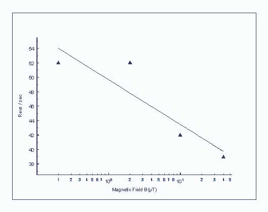
Figure 3. Interaction between the speed of vortexing and the magnetic field required to potentise.
5.6 Imprinting with A- & B- fields
The electric field (E-field) describes the mechanical force between electric charges, a magnetic field (B-field) arises when these charges are moving at a constant velocity, radiation occurs when the velocity changes. Figure 4 shows four coils in which a current flows in the direction of the arrows due to an electric field applied across the ends of the coil.
The solenoid generates a uniform magnetic field (B-field) within the coil, the lines describing this field pass along the axis and loop around the space outside the coil. Its magnetic field occurs in closed loops and is at right angles to the direction of the current.
The toroid contains the magnetic B-field within the torus. There is no external B-field but, there is an additional quantity called the magnetic vector potential (A-field) which is in the direction of the current and loops around and through the ring. This field can affect the phase of the wave function in a quantum system.
The Caduceus coil is a solenoid counter-wound back on itself so that the B-fields due to each half of the winding cancel. However, the A-fields rotate in opposite directions and generate a plane wave of A-field.
The Moebius coil is a loop with a twist in it so that the current is always in opposite directions in the upper and lower surfaces. Ideally, all the fields should cancel but the currents are only approximately coincident so there still could be a torque-like A-field.
Other arrangements such as a Helical Coil or Antonine Rings give more even complicated fields and effects.
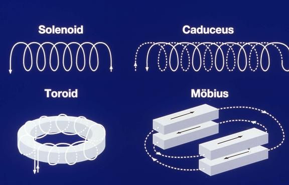
Figure 4. A diagram showing various coil arrangements
A solenoid can be used to potentise a frequency into water. The current needed in the coil depends on whether the geomagnetic field is parallel or perpendicular to the axis of the coil. It is more instructive to connect an oscillator to the toroid and generate a separate magnetic field with a solenoid. It is then found that the frequency of the water imprint is the frequency applied to the toroid. The solenoid can have a steady current or an alternating current. The B-field needed for potentising does not change with its frequency until the frequency reaches that applied to the toroid. It then ceases to potentise. This means that bio-information is carried by the magnetic vector potential (A-field) and the magnetic B-field performs a function analogous to that of formatting a computer disk.
The dimensions of the tube in which water is to be potentised affects the A– and B– fields required. There is an anomaly for potentising in a tube 2.5 mm diameter which disappears when the water is boiled enough to be air-free. Its diameter is a half-wavelength at the 60 GHz oxygen resonance. The length of the tube matters too; it was not possible to potentise water contained in a tube 21 cm in length; this corresponds to the wavelength of the 1.42 GHz molecular hydrogen resonance. Water placed in a resonator will potentise at the resonance if the Q-factor is sufficient [2] .
Although there are limits to the size of water droplets that can be potentised; water between the jaws of a precision micrometer could be potentised at a setting of 28µ but not at 26µ. This is consistent with the dimensions of a coherence domain as estimated in Section 4.6.
A drop of water previously frequency imprinted was placed between the jaws of a precision micrometer. The imprint was present down to 109µm but erasure had taken place by 108µm. This was independent of the frequency imprinted over the 13-decades from 10-4 Hz to 10+9 Hz. The threshold magnetic field for erasure gives a domain diameter of 52.9 µm compared with 108.5µm for the micrometer method. Therefore, it must be assumed that two domains (=106µm) are required for the retention of an existing potency in water between two metal surfaces.
A 2µl droplet of water was potentised and then divided in two portions 1cm apart. No imprint was detected in either. When the drops were recombined, the potentisation was again measurable. A spray of potentised water retains its potency when collected as a liquid. There must be a long-range interaction between small droplets of water.
5.7 Ferrite Toroids
Rings of ferrite material [3] can be used to copy and imprint potencies. Figure 5 shows two ferrite rings arranged to copy a potency in tube A into the receiving Tube B containing water ‘erased’ by placing briefly in a steel (“tin”) box to remove the Earth’s magnetic field. If Tube B itself contains any imprinting, this will be copied back into Tube A. Potentisation is effected by succussing on a wooden surface since the rings are ceramic and as fragile as glass. The coupling between the tubes is non-local and potentisation can be effected by succussing any one of the four items. This is useful if the receiver is a patient (patients would not like to be succussed!) or a plastic bottle.
Figure 6 shows the arrangement using a single toroid. This inverts the imprint from stimulatory to depressive (or vice-versa). One practical application is to take a nasal swab from a patient with allergic rhinitis, place it in position A on a piece of wood which is positioned so that the patient’s nose comes at position B. The toroid is succussed. In one case, the patient returned at the next pollen season for a repeat treatment, the previous year’s had held throughout.
This technique should avoid regulatory problems associated with the potentisation of nosodes since no chemical contact is involved.
A hexagonal arrangement of 5 toroids around a cell culture will suppress frequency activity and stop growth.

Figure 5. Two ferrite rings arranged to copy a potency in tube A into ‘erased’ water in Tube B.
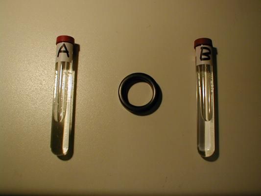
Figure 6. A single ferrite ring copies with inversion from stimulatory to depressive and vice-versa.
5.8 Digital Potentisation with Calculator, Computer or Electrical Pulses.
The writer has shown that the basic arithmetical operations can be performed on frequencies imprinted into water and using somewhat similar arrangements that the basic reversible logic gates and their operations also can be implemented.
This means that any reversible Boolean function can be computed by such reversible logic gates N (not), CN (control-not) and CCN(control-control-not). With reversible logic gates, knowledge of the output states enable one to determine the input states unambiguously; irreversibility leads to de-coherence and thermal dissipation. Such operations could be triggered by a train of seven voltage impulses acting as clock pulses. The outcome depends on the spatial arrangement of the water aliquots thereby implying that there is a macroscopic wave function interaction [4] , [5] . The required voltage threshold is low enough for a train of 110 mV nerve impulses to be able to trigger such operations in cells at nerve endings. Frequency is the coding for bio-information. Each frequency is processed separately which allows for parallel processing in a live bio-computer. Homeopathic potencies would represent data inputs.
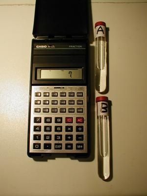
Figure 7. A potency in Tube A can be copied into Tube B by pulses from a calculator.
Potentisation can be effected with a calculator by placing Tubes A and B next to it as shown in Figure 7. A potency in Tube A can be copied into Tube B by pulses from a calculator. It only requires 7 uni-directional voltage pulses to effect this imprinting. The necessary pulse train is generated in this calculator by entering ‘7’ and then pressing ‘=’ .
To copy as a different potency, key in 10. for D potencies, 100. for C potencies and 1000. for M potencies. Follow the decimal point by the number of the potency e.g. 10.6 for a D6 potency. Then finish with the 7= .
A mobile phone can replace the calculator. Calling-up a number with at least 7 digits will effect copying. However, it will also copy the mobile frequencies into the hand and head of the user. This takes about 15 minutes to clear from the body.
A computer can also be used to potentise between tubes placed alongside. Here the appropriate codes must be worked out for an individual system.
For example, the sequence CTRL A / SHIFT S / CTRL * / SHIFT U can effect a copy where * represents the letters giving the multiplying factor e.g. A =1, B=2, C=3,…..J =10.
In BASIC, the appropriate ASCII code can be realised by using PRINT for a sequence of chr$(number) terms.
An electroacupuncture apparatus can potentise water placed inside a brass beaker or ‘matrix’ connected to the output. Although, if the output is viewed with an oscilloscope, only noise is visible.
Merely tapping a lead connecting to the brass beaker on the terminal of a 1.5V battery seven times will effect a copy from a potency in a similar beaker connected to it. The transmission of coherence along a wire is blocked if a 3A fuse is inserted in the path, a 10A fuse has wire of sufficient diameter to pass the signal.
Potency information can be digitised and stored in any computer storage medium. The late Jacques Benveniste [6] was so successful at the transmission and recovery of bio-information that he called down the ‘wrath-of-the-gods’ on his head.
5.9 Chemical potentisation.
The potentisation of a solution of hydrogen peroxide results in a continuum of stimulating (therapeutic) frequencies which is the nearest I have found to water imprinted by a healer. Warning, the potentisation of formaldehyde results in a continuum of stress.
Lead metal has an endogenous frequency which can effect a potentisation. To demonstrate this, take a beaker of erased water and place in it a glass tube containing a piece of lead (or lead-tin solder), a glass tube containing a potency and a glass receiving tube containing the erased water to be potentised. Add one drop of 3% solution of hydrogen peroxide to the beaker. The potency will have copied into the water in the beaker and into receiving tube.
5.10 Imprinting and the Environment
5.10.1 Double-Blinded or Wide Eyed?
There is no point in trying to do ‘Double-Blinded’ trials of homeopathic potencies if the protocol cannot be made to work when the identity of the specimens is known.
Taking a set of 10 tubes of erased water, 1 kHz was imprinted into the odd numbered tubes and nothing into the even numbered tubes. This is shown yellow in the top row of Table 1. The results of the measurements are shown green if as imprinted or red if wrong. The first measurement run was correct up to tube 6, then tubes 7 and 8 went wrong.
Things got worse in measurement run #2 but improved slightly in runs #3 and #4. Before run #5, the measurement space was gone-over with a small hand-held vacuum cleaner, after which run #5 appeared all green. This was not maintained, the last tube in run #6 went wrong and there were three wrong results in run #7.
Table 1.
| Tube Numbers | 1 | 2 | 3 | 4 | 5 | 6 | 7 | 8 | 9 | 10 |
| Imprinting | 1 | 0 | 1 | 0 | 1 | 0 | 1 | 0 | 1 | 0 |
| Measurement #1 | 1 | 0 | 1 | 0 | 1 | 0 | 0 | 1 | 1 | 0 |
| Measurement #2 | 0 | 1 | 0 | 0 | 1 | 1 | 0 | 0 | 1 | 1 |
| Measurement #3 | 0 | 0 | 1 | 1 | 1 | 0 | 1 | 0 | 0 | 0 |
| Measurement #4 | 0 | 0 | 1 | 0 | 1 | 0 | 1 | 1 | 1 | 1 |
| Measurement #5(space vacuumed) | 1 | 0 | 1 | 0 | 1 | 0 | 1 | 0 | 1 | 0 |
| Measurement #6 | 1 | 0 | 1 | 0 | 1 | 0 | 1 | 0 | 1 | 1 |
| Measurement #7 | 1 | 1 | 0 | 0 | 0 | 0 | 1 | 0 | 1 | 0 |
On moving the tubes away from the toroid, the results became correct at a distance of 39 cm. This suggests a zone existed within which the measurements were anomalous. The zone space was checked at 5 min. and 20 min. and the anomaly was still there. It was then left undisturbed overnight and it was still there after 12 hours. It seems to be possible to walk into and out of the zone without disturbing it. This suggests that a potentisation of the space had taken place and that the effect was not going to decay with time.
If Tube B in Figure 5 is replaced by sealed plastic bag of ambient air this can be potentised but, it requires the air to be humid. If some silica gel is put in the bag, no potentisation is possible.
This sequential measurement procedure seems to be the way to set up such an anomalous potentised zone. A set of 9 frequencies from 10-4 Hz to 10+4 Hz was imprinted into a single tube. All these frequencies were read correctly and this was repeated this more than six times. All readings were correct and no anomalous zone appeared. The anomaly seems to be associated with measurements on numbers of distinct specimens. Within a zone it is not possible to determine which of the 10 tubes is actually being measured.
The distance 39 cm is exactly a half-wavelength of 78 cm which is the wavelength of the upper-band heart meridian frequency 384 MHz (3 × 10+8 / 3.84 × 10+8 = 0.78 m). The velocity of propagation of coherence in air is 0.05 m/s [7] . For a zone of diameter 0.78 m there should be a resonance in the coherence at 6.4× 10⁻² Hz. Measurement within the zone found a resonance at 6.413 × 10⁻² Hz. This resonance disappeared when a fan was switched to produce an air velocity and turbulence greater than the coherence velocity.
However, all was not solved. Leaving the fan on while repeating measurements as in the above Table gave 3 correct runs. At the 4th. run – every tube was erased, nothing was left to measure at all in any of the 10 tubes.
Likewise, it seemed a simple idea to move the set of 10 tubes more than 39 cm away and bring them up one at a time for measurement. This gave 3 correct runs but at the 4th. run the zone had enlarged to 156 cm radius (= 4× 39 cm) to encompass the new location of the tubes and all the anomalies returned.
The zone also gives anomalous imprinting so the effect could be very relevant to homeopathic potentisations. I set up an anomalous zone as above and then tried to imprint a tube of water at 1 kHz within it. After succussion, there was no 1 kHz but a set of three frequencies. The three frequencies were those of the Sanjiao, Heart and Nerve Degeneration acupuncture meridians, the latter being Voll’s summation point for the entire ANS.
This is clearly an objective manifestation of a subjective effect related to the heart meridian which also covers consciousness and mental activity. The following procedure demonstrates that this is an experimenter induced effect.
- Tube: ‘1’ in Figure 8 is frequency imprinted, Tube ‘0’ contains erased water.
- Tube 1 is moved by hand to position A this is repeated 7-times. Tube 1 has then lost its imprint and Tube 0 acquires its imprint. This change persists out to 78 cm (wavelength of 384 MHz) from the toroid. Beyond this both are in their original state.
- Move Tube 1 by hand to position B 7-times (or more) there is no effect. The tube must cross to position A.
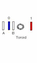
Figure 8. Positions of Tubes
To confirm that this was an operator induced effect, the hand movement was replaced by having Tube 1 suspended as a pendulum so that it swung from position 1 to position A to-and-fro many times with the experimenter standing well back after starting the pendulum swinging. There was no change in either tube confirming that this effect is experimenter induced.
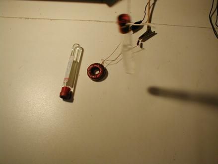
Figure 9. Tube 1 swinging over Tube 2 with experimenter at a distance.
Something that that does seem to isolate the specimens from the effect is a large piece of aluminium foil placed under and folded over the specimens while a measurement is being made on one of them and while it is being moved about as in Figure 10.
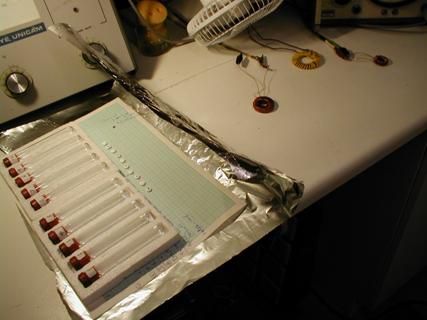
Figure 10. Tubes and potencies in aluminium foil wrapping.
For trials on homeopathic potencies, tablets of Phosphorous 6C conveniently contain the (UK) power supply frequency 50 Hz so that any mains electrical device can be used to excite them. These can be seen beside the tubes in Figure 10. Alternate tablets have been marked with a pen, all these tablets had been erased. All tablets can be turned over so as to appear identical for blind selection.
5.10.2 Potentisation from Over-Head Power Lines
Each set of three conductors (the phases) of the typical overhead power line represents a three-phase transmission system, there are two in Figure 11. The term phase has a double use. In power systems it denotes an electrical circuit. It also denotes the fraction of a cycle of the supply frequency (50 Hz in the UK, 60 Hz in N. America) by which the voltages and currents in the conductors differ. This is expressed as an angle in degrees, 360º represents a complete cycle and equals phase angle 0º.
The magnetic field (B) and the magnetic vector potential (A) are both proportional to the current in a long straight wire. When one is far enough away from a set of three-phase conductors, each conductor can be regarded as at the same distance, the vector sum of the phase currents will be zero and B and A will be zero.
Directly beneath the centre of the conductors of a typical 400 kV line, there could be a 40% difference between the distance from the lower conductor and the mean distance of the two upper ones. Here, B and A would have values corresponding to 40% of the line current for a single conductor. The actual value obviously depends on the line configuration and the terrain.
Imprinting a frequency into water requires an alternating magnetic vector potential (A) at that frequency and a magnetic field at any frequency less than or equal to this. Close to overhead lines, the effect of the unbalance of distance may be sufficient to imprint water.
For a 400kV twin-conductor, double circuit transmission line, water would spontaneously and immediately imprint at distances of 40 to 50 metres on either side of the line-centre. The frequencies imprinted into water so exposed were: 50 Hz, 150 Hz, 16.66 Hz and 3 Hz. These represent the UK power supply frequency, the third and one-third harmonics and what is probably a load fluctuation at 3 Hz.
This water imprint was like that found when potentised water has been heated above 90ºC. It is only detectable with a Caduceus coil but it may be restored to its usual form by 7.8 Hz which is the endogenous frequency of the heart chakra. This may be done by placing it close to a coil radiating that frequency or by holding the tube against the heart chakra.
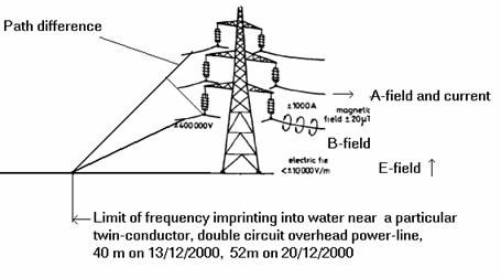 |
Figure 11. Fields near overhead power lines
5.10.3 Distance Related Potentising near Transmitters
A Study reported in a paper [8] on, “Cancer Incidence near Radio and Television Transmitters in Great Britain II. All High Power Transmitters” was concerned with, ‘…findings for adult leukemias, skin melanoma, and bladder cancer near the 20 (other) high power radio and TV transmitters in Great Britain…’ (i.e. other than the Sutton Coldfield transmitter which had been studied previously). It concluded that, “….while there is evidence of a decline in leukemia risk with distance from transmitters, the pattern and magnitude of risk associated with residence near the Sutton Coldfield transmitter do not appear to be replicated around other transmitters”. This Study and its findings were at odds with the ‘gut-feelings’ of local residents which they communicated to the writer who re-examined the published data in the simplest manner [9] .
The observed-to-expected (O/E) ratio values do show an O/E peak which may represent a “window” for electromagnetic field effects; any peak in the original “Study” results is minimal. A probability plot (Figure 12) gives a good fit to a ‘Normal’ distribution from 1.5 km to 8 km with the mean close to 5 km and a standard deviation of ± 1.5 km.
Since the Study covered 20 transmitters from different parts of the UK, it is reasonable to assume that any effects related to geographical or topographical features and antenna design would average out. This only leaves the physical characteristics of the propagation of electromagnetic radiation from which to seek a mechanism.
 |
Figure 12. Probability plot of cancer data versus distance from 20 transmitters.
A simple experiment involving a toroid and solenoid connected in series showed that when the A and B field vectors are in opposition (180º or p/2 phase difference) the frequency of the current is imprinted into nearby water. When the A and B fields are parallel (zero phase difference) that frequency imprint is erased.
The electromagnetic radiation (E– and B-fields) from a transmitter will experience the refractive index of air and propagate at the velocity of light in air. The magnetic vector potential (A-field) does not interact with the air propagates at the vacuum velocity of light. At 5 km distance from the transmitter, there is a transit time difference of 5 ns between the A and B fields. At 100 MHz this represents a 180º or p/2 phase difference. This is the condition for that frequency to be imprinted into any water or living tissues. The frequency band 70MHz-130MHz covers the standard deviation in Figure 12 and includes the FM radio transmissions from the TV transmitter towers.
5.11 Where does the Information in a Potency come from?
Having discussed various methods of potentising, the final question is where does the bio-information that goes into a homeopathic potency come from?
Because of the fractality of frequency in a coherent system, it is possible to make plastic stick models of molecules and measure their characteristic frequencies. The molecular model needs to be immersed in saline giving the correct velocity of coherence propagation for the fractal frequency effect to occur. A stick model scaling length at 3cm/Ã… scales the velocities by a factor 108 from the velocity of coherence in saline 3 m/s to the velocity of light in free space. 300 Mm/s. The plastic molecular models merely produce a pattern of discontinuities in the water at the interface. Table 2 shows the frequencies for such molecular models of n-hexane. The best fit for the frequencies comes from the model in Figure 13 which corresponds to n-hexane with hydrogen-bonded water extending the whole length of the molecule.
The first column in Table 2 lists the ELF signature frequencies for the chemical n-hexane, the second and third columns give the frequencies measured for molecular models of n-hexane in saline. Four H-bonded water molecules are shown joined to carbon atoms 1 and 6. This arrangement matches the frequency pattern measured for n-hexane with trace water.
Table 2
Modelling n-Hexane
|
Chemical n-hexane + trace water |
Model C6H14only | Model C6H14 + 4 H2Obridging C1 – C6 |
| Hz | Hz | Hz |
| 4.2 | 4.113 | 4.204 |
| 6.8 | 7.132 | 6.824 |
| 13 | 20.31 | 13.10 |
| 19.4 | 38.11 | 19.32 |
| 26 | 80.32 | 25.32 |
| 42 | 41.63 |
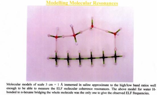
Figure 13.
Conclusion
Life in the present chemical and electromagnetic polluted environment needs an understanding and application of homeopathy to recognise, identify and correct proving symptoms arising from the mass medication by the pollution.
In these Chapters, I have tried to present a theory of homeopathy based on existing physics with no new science and in a form which should make it possible to ‘attempt to disprove’ the hypotheses in the spirit of Karl Popper.
I will present a short non-mathematical executive summary as the next Chapter.
[1] Agilent 33250A Function/Arbitrary Waveform Generator (www.agilent.com)
[2] Cardella C, de Magistris L, Florio E and Smith CW. (2001) Permanent Changes in the Physico-Chemical Properties of Water Following Exposure to Resonant Circuits. Journal of Scientific Exploration 15(4): 501-518 (2001). Correspondence: 16(2): 256-259 (2002).
[3] Maplin ferrite ring #QT26D is a convenient size to handle. www.maplin.co.uk
[4] Smith C.W. (2001) Learning from Water, a Possible Quantum Computing Medium, 5th. International Conference on “Computing Anticipatory Systems”, HEC Liège, Belgium, 13-18 August 2001. CASYS’01 Abstracts – Symposium 10, p.19. Intl. J. of Computing Anticipatory Systems 13:406-420 (2002).
[5] Smith C.W. (2005) Watergates – Logic Operations in Water, 7th. International Conference on “Computing Anticipatory Systems”, HEC Liège, Belgium, 8 – 13 August 2005. CASYS’05 Abstracts – Symposium 10, p. 9.
[6] www.digibio.com
[7] Smith CW. Coherence in Living Biological Systems. Neural Network World 3: 379-388, 1994.
[8] Dolk, H., Elliott, P., Shaddick, G., Walls, P. and Thakrar, B, 1997, Cancer Incidence near Radio and Television Transmitters in Great Britain II. All High Power Transmitters. American Journal of Epidemiology, 145(1) : pp.10-17.
[9] Smith C.W. (2001) Distance -related effects near radio and TV transmitters, Electromagnetic Hazard & Therapy 11(2-4):10-11.
——————————————————
Cyril Smith was born in London, England, in 1930. He started work in radar in 1947; he was a Research Fellow at Imperial College, London, from 1956 under Blackett and McGee working on Medical X-ray Images. From 1964 at Salford University in the Electrical Engineering Department, his research activity included: Instrument Technology, Medical Electronics, Dielectric Liquids, Electromagnetic Effects in Living Systems and Water. In 1973, his co-operation with Herbert Froehlich, FRS commenced. In 1982, he first became involved with the diagnosis and treatment of electromagnetically hypersensitive patients. He was Secretary of The Dielectrics Society from 1972-1983. In 1989/90, his co-authored book “Electromagnetic Man” was published. That year he also took early retirement. He continues to be active in research and writing.


Dear Dr Smith,
Please visit my webpage http://www.neohahnemannism.com and go through my article “Hahnemann was the father of modern Molecular Medicine”, which is semi-popular form of some scientific articles already published in medical journal. You are earnestly requested to send your valuable opinion.
With Regards
Yours truly
Dr Sanjib Chattopadhyay
Associate Professor,
Dept of Zoology,
BKC College
Kolkata 700108
India