

The alteration in orientations of water molecules is one of nature’s gifts that not only help explain Homeopathy but also help explain many other phenomena, such as Electrical Earthing.
What is electrical earthing? It is the separate path (third wire) through which any leakage in current due to faulty appliances or imperfect electrical connections returns to the earth without causing any hazard to the user. If there is proper earthing (grounding) at the user’s end, it will prevent fatal accidents. The question is, how does the earth help passage of current and what is the ultimate fate of such current. It is often explained that the leaked current is returned to the source through an earth wire (i.e; earth acting as wire) as shown in figure 1. The Earth wire being a separate / alternate path for return of electrical energy through the grounded rod at the user’s end to the grounded rod of the source (i.e; generating unit).
When one is working with a line tester, one notes the presence or absence of current in a circuit. Usually the phase line is tested by a line tester. The user can test the presence or absence of current even by standing on the ground, as earth is believed to be at the negative potential (i.e., it acts as a huge source of electrons). It is also believed that as the lamp used in the tester is a very low voltage lamp and takes very little current to light, the capacitance of the user’s body to earth ground is sufficient to complete the circuit and light the tester.
Here, we present some of our observations to support our idea that the electrical properties of water are responsible for conveying the electrical energy of a substance through change in its orientations of water molecules. This helps explain how homeopathic remedies act in liquid , solid or Imponderabilia 1,2.
Experiment1: A line tester (screw driver type) is inserted into the hole (phase line) of a socket and found to glow when the user touches its tip with his finger (Fig 1). This tester however not only works in the ground floor but even works in 1st,2nd 3rd and even further.
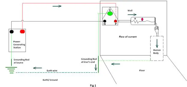
Discussion: It is said that the circuit is completed through the user’s body to the earth and the earth acts as a wire for conveyance of electrical energy between the user and the source. It is agreed that earth wire is conveying current between the user and the source in case of the ground floor, but how is the electrical energy conducted when the user on the 1st, 2nd, 3rd or higher floors. More clearly, how is the electrical energy conducted from the higher floors to the ground floor before being conducted to the source through the earth wire?
Experiment 2: A line tester (screw driver type) is inserted into the hole (phase line) of a socket. Now instead of the human body, a wire is connected to the tip of the line tester. The other end of the wire is connected to a graphite electrode and placed on the wall at different heights from the ground. A drop of water is poured on the junction of the graphite electrode and the wall (cemented wall) and the condition of the line tester noted before and after the (distilled) water for different heights (table below).
| Sl. No. | Height (in cms) from ground | Condition of the Line tester | |
| Before pouring a drop of distilled water | After pouring of a drop of distilled water | ||
| 1 | 90 | glows poorly | Glows brightly |
| 2 | 120 | glows poorly | Glows brightly |
| 3 | 150 | glows poorly | Glows brightly |
| 4 | 180 | glows poorly | Glows brightly |
| 5 | 210 | glows poorly | Glows brightly |
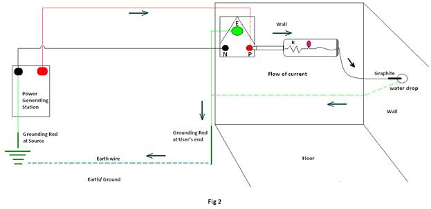
Discussion: In experiment 1 the circuit is completed through the user’s body to the Earth. But here there is no contact between the user’s body and the line tester. Still the line tester glows brightly. This demonstrates that it’s not the human body which is responsible for glowing of the line tester, but something that is present in the wall and acting as a conductor of electrical energy. It can be said that capillary water present in the wall helps conduction of electrical energy from a wall of any height (as long as water molecules are present) to the ground and thereafter through the earth wire to the source.
Experiment 3; A line tester (screw driver type) is inserted into the hole (phase line) of a socket. A wire is connected to the tip of the line tester. The other end of the wire is connected to a graphite electrode and instead of placing the electrode on the wall of the same building, it is placed outside the building. The line tester glows brightly.
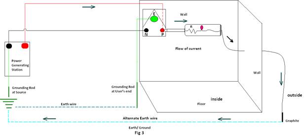
Discussion: This experiment is done to show that the tester even glows without using earthing (grounding) of the building or the earth wire. The question is, how is the circuit completed for the glowing of the Line tester. This experiment confirms that the earthing rod of the building is not responsible for the flow of electrical energy and hence the glowing of the tester is due to the alternate Earth wire formed between the graphite (acting as grounding rod at user’s end) and the grounding rod of the source. In other words the water molecules in between the graphite and the grounded rod of the source, help in completion of the circuit and flow of electrical energy.
From the above it is clear that water molecules are actually carriers of electrical energy in the case of Electrical earthing. We have explained earlier that ions are not the carriers of electrical energy, either in water or aqueous solution3,4. Thus in household electrical earthing also, it is not the ions, but orientations of water molecules that are the carrier of electrical energy.
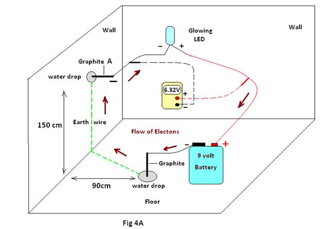
Experiment 4: This experiment is performed to show that earth neither donates nor accepts electrons, but only helps in the flow of electrical energy due to the presence of water.
Case 1: The positive terminal of a battery (9 volts) is connected to the positive end of the LED (as shown in Fig4A). The negative terminal of the LED is connected to the wall through a graphite electrode and a drop of distilled water is placed at the junction of the graphite and the wall. The LED does not glow. This suggests that the earth does not provide any electrons on its own.
Moreover, as soon as the negative terminal of the battery is connected to the earth through a graphite electrode placed on the floor (the earth) and a drop of distilled water is placed at the junction of the electrode and floor, the LED glows brightly. The potential difference between positive terminal of the battery and wall (the Earth) is measured and found to be 6.32 volts with the earth as negative end. In other words, the earth seems to have negative potential and is supplying electrons.
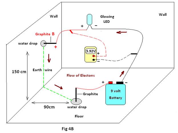
Case 2: The negative terminal of the battery (9 volts) is only connected to the negative end of the LED (Fig 4B). The positive terminal of the LED is connected to the wall/earth through a graphite electrode (Graphite B) and a drop of distilled water is placed at the junction of the graphite and the wall. The LED does not glow, which means the earth does not accept any electrons on its own.
Moreover, as soon as the positive terminal of the battery is connected to the earth through an electrode placed on the floor (the earth) and a drop of distilled water is placed at the junction of the graphite and floor, the LED glows brightly. The potential difference between the negative terminal of Battery and the Earth is measured and found to be 5.92volts, with earth as positive end (Graphite B). Therefore, the earth seems to have a positive potential and is accepting electrons.
Case 3: In this case the conditions for case 1 and case 2 are applied simultaneously, keeping distance (about 120cm) between the two drops of water. (as shown in Fig 4C).
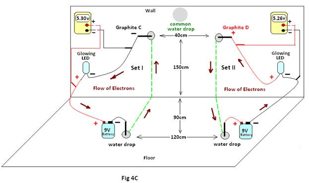
Results & Discussion : From case 1 & case 2 of experiment #4, it is quite clear that the earth is neither at positive nor at negative potential. It only acts as a source or sink for electrons when any source of electrons (as the 9 volt battery in experiment #4) is connected to it5. In case #3, it is found that not only does the LED glow simultaneously in both sets, but sufficient potential difference is recorded for the two conditions – Set I & Set II being 5.30 volts and 5.26 volts respectively. Now, for Set I at Graphite C, the earth behaves as if at negative potential and for Set II at Graphite D, for positive potential simultaneously. Moreover, on placing of both Graphite C & Graphite D on the point denoted as “common water drop”, similar results are obtained i.e ; both the LEDS glow simultaneously .
These results again confirm that the earth can be at positive potential, negative potential or both simultaneously, depending on the terminal of the source (positive or negative) to which it is connected. The effect of a series connection between the two batteries, through water drops (distance 120 cm apart) and connection in between two Graphites, Graphite C & D ( distance 40 cm apart), though little, is only due to the presence of capillary water. From the above it is clear that no electrical potential can be assigned to the earth, as it is only a conductor of electrical energy, owing to the presence of water5.
Inference:
i) Like many other natural phenomenon the secret behind Electrical Earthing is nothing but orientations of water molecules. The electrical potential of the earth is not absolute as previously thought, but is relative, i.e. it acts as a source or sink of electrons only when a source of electrical energy is connected to it.
Reference:
[1] The electrical energy of substances –the secret of homeopathy, Ruhul Amin & Biplab Chakraborty (Simillimum,vol.XXII, Summer Fall/ 2009 www.hanp.net)
[2] Electromagnetic radiation as a source of homeopathic medicine-Imponderablias – Ruhul Amin & Biplab Chakraborty(Published in Homeopathy For Everyone Mar 2012 hpathy.com
[3] Solutions Ionic or Non-ionic Conducts & Retain Electrical Energy. Ruhul Amin & Biplab Chakraborty(Published in Homeopathy for Everyone July 2012 hpathy.com
[4] The key to the Homeopathic dilution, Ruhul Amin & Biplab Chakraborty (Published in Homeopathy for Everyone Nov 2012 hpathy.com)
[5] Orientations of water molecules-the force behind Homeopathy. Ruhul Amin & Biplab Chakraborty (Published in Homeopathy for Everyone Apr 2013 hpathy.com)


Hi Mr Ruhul Amin, I am very interested in your publications. Also, I would like to get your email address to talk to you about some project I have where I could benefit from your advices, maybe in a consulting approach. Do you mind to send it to me: in general, one project is about the deterioration / conservation of the information contained in homeopathic remedies.
At the end of this year, I plan to create a new company just for the purpose of this, involving also biophoton analysis. Thank you in advance